Utility Trench Excavation & Pipe Bedding Calculator
Calculate high-precision trapezoidal trench excavation volumes, OSHA soil slope benching, pipe barrel displacement deductions, aggregate bedding stone tonnage, and native backfill quantities for water, sewer, and storm utility bids.
How Is Utility Trench Excavation and Bedding Calculated in Civil Estimating?
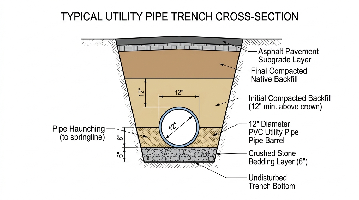
Utility trench excavation volume is calculated using the trapezoidal prismoidal formula: Volume (CY) = [(Bottom Width + Top Width) / 2 × Depth × Length] / 27, where the top width is dictated by OSHA 1926 Subpart P soil sloping requirements (Type A at 0.75:1, Type B at 1:1, or Type C at 1.5:1) unless a certified steel trench shield is utilized. Imported bedding stone tonnage is quantified by calculating the gross trench bedding envelope (bedding depth beneath the barrel plus pipe zone haunching up to 12 inches above pipe crown), deducting the physical cylindrical displacement of the pipe exterior (π × r² × L), and multiplying by the compacted aggregate density (typically 1.35 to 1.45 tons per cubic yard).
Utility Trench Excavation & Bedding Calculator
1. Pipe & Trench Dimensions
2. Bedding & Shoring Parameters
Calculated Material & Hauling Takeoff
Need complete pipe run stationing, invert profiles, and structure schedules for an upcoming utility bid?
Principles of CSI Division 33 Trench Quantification
In underground utility contracting, trench excavation is rarely a rectangular trench cut. In practical field operations, trench dimensions, safety shoring requirements, aggregate backfill imports, and spoil hauling are governed by pipe diameter, geotechnical soil stability, depth to invert, and municipal standard details.
1. The Four Standard Depth Cut Stratifications
Civil engineering contracts and DOT standard specifications require estimators to categorize linear footage of underground pipe runs into standardized depth brackets. Excavator cycle times and daily linear production decline exponentially as trench depths increase:
| Depth Cut Bracket | Excavation Method | Safety / Shoring Requirement | Daily Production Impact |
|---|---|---|---|
| 0 to 6 Feet (Shallow) | Direct bucket cut with standard excavator | Vertical cut allowed up to 5 ft (OSHA); minimal sloping | 100% baseline production (300–500 LF/day) |
| 6 to 10 Feet (Medium) | Trapezoidal bench or standard trench shield | Mandatory OSHA Type B/C slope or 8'x20' trench box | 70%–80% baseline production (200–300 LF/day) |
| 10 to 14 Feet (Deep) | Heavy excavator (CAT 336/349) with stacked boxes | Stacked trench shields or slide-rail shoring systems | 45%–60% baseline production (120–180 LF/day) |
| 14+ Feet (Extreme) | Two-pass excavation or benching platform | Engineered shoring, tight sheeting, or heavy slide rail | 25%–40% baseline production (< 100 LF/day) |
OSHA 1926 Subpart P Soil Classification & Sloping Ratios
When trench boxes cannot be used due to crossing utilities, lateral sewer services, or wide open easements, the trench walls must be sloped back in compliance with federal safety regulations:
- Solid Rock: Vertical trench walls (90°). Zero lateral slope addition.
- OSHA Type A Soil (Cohesive Clays, Hardpan): 0.75:1 slope (53°). Top width expands by 1.5 × Depth.
- OSHA Type B Soil (Silt Loam, Sandy Clay, Fissured Clay): 1:1 slope (45°). Top width expands by 2.0 × Depth.
- OSHA Type C Soil (Gravel, Clean Sand, Submerged Soil): 1.5:1 slope (34°). Top width expands by 3.0 × Depth.
Governing Mathematical Formulas
Detailed Trench Geometry Equations
- Top Trench Width (W_top): W_top = W_bottom + [2 × (Depth × Slope Ratio)]
- Gross Trench Excavation: CY = [((W_bottom + W_top) / 2) × Depth × Length] / 27
- Cylindrical Pipe Displacement: CY = [π × (OD / 2)² × Length] / 27
- Gross Bedding Envelope: CY = [W_bottom × (Bedding Depth + OD + Cover Depth) × Length] / 27
- Net Crushed Stone Bedding: Tons = (Gross Bedding Envelope - Pipe Displacement) × Stone Density (Tons/CY) × (1 + Waste)
- Net Native Backfill Volume: CY = Gross Excavation - Gross Bedding Envelope
Pipe Outside Diameter (OD) vs. Nominal Diameter Reference
Estimators often mistakenly use inside nominal pipe diameter when computing displacement. The outside barrel dimension must always be used:
| Nominal Diameter | C900 PVC (DR18) OD | DIP (Class 50/52) OD | RCP (Class III/IV) OD | Dual-Wall HDPE OD |
|---|---|---|---|---|
| 8-Inch | 9.05 inches | 9.05 inches | 12.00 inches | 9.80 inches |
| 12-Inch | 13.20 inches | 13.20 inches | 16.50 inches | 14.50 inches |
| 18-Inch | 19.50 inches | 19.50 inches | 23.50 inches | 21.50 inches |
| 24-Inch | 25.80 inches | 25.80 inches | 30.00 inches | 28.50 inches |
| 36-Inch | 38.30 inches | 38.30 inches | 44.00 inches | 42.00 inches |
Step-by-Step Worked Estimating Example
Consider a commercial storm sewer trunkline consisting of 800 LF of 24-inch Reinforced Concrete Pipe (RCP) installed in OSHA Type B cohesive soil at an average invert depth of 8.5 feet:
- Pipe Barrel OD: 30.0 inches (2.50 feet)
- Trench Bottom Width: 5.0 feet (permits 15 inches of clearance on each side of barrel)
- Bedding Specification: 6 inches ASTM #57 stone bedding beneath barrel; 12 inches cover over pipe crown
- Bedding Stone Unit Weight: 1.40 tons per compacted cubic yard; 8% material handling waste
- Excavation Mode: 8-foot wide steel trench shield (near-vertical trench profile)
Step 1: Compute Total Trench Excavation
Trench Cut = [5.0 ft width × 8.5 ft depth × 800 ft length] / 27 = 1,259.3 BCY
Step 2: Compute Total Pipe Barrel Displacement
Pipe Radius = 2.50 ft / 2 = 1.25 ft
Pipe Volume = [π × (1.25)² × 800 ft] / 27 = 145.4 CY of Displacement
Step 3: Calculate Net Crushed Stone Bedding Tonnage
Total Bedding Envelope Depth = 0.5 ft bedding + 2.5 ft pipe + 1.0 ft cover = 4.0 ft
Gross Envelope Volume = [5.0 ft × 4.0 ft × 800 ft] / 27 = 592.6 CY
Net Bedding CY = 592.6 CY - 145.4 CY displacement = 447.2 CY
Bedding Stone Tons = 447.2 CY × 1.40 tons/CY × 1.08 waste = 676.1 Tons of ASTM #57 Stone
Step 4: Compute Native Backfill & Spoil Export Balance
Remaining Trench Backfill = 1,259.3 BCY cut - 592.6 CY stone envelope = 666.7 CY of native backfill
Surplus Native Soil to Export = 592.6 CY displaced by stone & pipe × 1.25 swell = 740.8 LCY (46 Dump Truckloads)
Common Trench Estimating Mistakes to Avoid
1. Missing Bell Hole Excavation Allowances
Ductile iron and PVC pipe joints require localized bell-hole depressions at every 18-to-20-foot pipe joint for assembly and torque verification. Ignoring bell holes understates labor and bedding stone quantities.
2. Ignoring Pavement Sawcutting on Replacement Lines
Installing utilities through existing asphalt parking lots requires dual full-depth sawcut linear feet (2 × Length), pavement demolition tonnage, and controlled low-strength flowable fill backfill beneath traffic lanes.
3. Underestimating Trench Shield Widths
A 6-foot inside-dimension trench box has 6-inch to 8-inch steel side walls. The actual excavation bucket cut must be 7.5 to 8.0 feet wide, dramatically increasing total yardage and stone backfill over plan dimensions.
4. Overlooking Trench Rock Refusal Depths
If geotechnical boring logs indicate bedrock at 6 feet and your storm sewer invert runs at 10 feet, 4 vertical feet of hard rock must be excavated using hydraulic hoe-ram breakers or drill-and-blast methods, adding 3x to 5x cost per linear foot.
Frequently Asked Questions (AEO & Field Standards)
What is the standard bedding thickness under utility pipes?
Standard municipal specifications mandate 4 inches of aggregate bedding for pipe diameters up to 12 inches, and 6 inches of crushed stone bedding for pipes 15 inches through 36 inches. In rock trench conditions, minimum bedding depth increases to 6 inches or 1/12th of the pipe outside diameter to prevent point-loading on bedrock fractures.
How do you calculate concrete thrust blocks for water mains?
Thrust blocks are required at all changes in direction (bends, tees, dead-ends, and valves). The thrust force is calculated as Thrust Force = 2 × Area × Pressure × sin(θ / 2), where Area is pipe cross-sectional area, Pressure is test pressure (typically 150–200 PSI), and θ is bend angle. Estimators compute bearing area against undisturbed trench walls to determine cubic yards of 3,000 PSI thrust block concrete.
When is flowable fill required instead of native trench backfill?
Controlled Low-Strength Material (CLSM / flowable fill) is required by state DOTs and municipalities whenever utility trenches cross beneath existing asphalt roadways, concrete sidewalks, or parking driving lanes. Flowable fill eliminates settlement risks and avoids the labor of hand-tamping native backfill in thin 6-inch lifts.
Related Underground Utility Services & Guides
Underground Utility Takeoff Services
Professional takeoffs for domestic water mains, sanitary gravity sewer, storm sewer trunklines, and detention structures with depth stratification.
ENGINEERING GUIDEUtility Trench Safety & Shoring Guide
In-depth review of OSHA excavation safety standards, slide rail shoring, hydraulic vertical shores, and dewatering trench sumps.
Need a Complete Wet Utility Takeoff for Bid Day?
Upload your utility plans and civil profiles. We provide itemized pipe run schedules, manhole depth tallies, and bedding material spreadsheets in 24 to 48 hours.