How Sitework Estimating Works: The 4-Step Process
We operate as a seamless extension of your pre-construction estimating team. Here is exactly how we take your raw civil blueprints and transform them into verifiable, bid-ready numbers.
Submit Civil Drawings & Bid Parameters
Upload your project drawing files via our secure plan portal. While PDF vector drawings are our most common input format, providing AutoCAD (.dwg) or LandXML files can help accelerate surface extraction.
- Civil Grading & Drainage Plan (C-200 series) with readable contour labels
- Utility Plan and Profiles (C-300 series) with structure invert tables
- Paving details showing pavement, stone base, and curb cross-sections
- Geotechnical Soils Boring Report (critical for rock, groundwater & shrink/swell)
Sheet Audit & Fixed-Fee Quote
Our civil estimators review the drawing set to ensure all sheets and addenda are accounted for. We determine the exact scope required (Division 31 Earthwork, Division 32 Exterior Improvements, Division 33 Utilities) and send you a formal, fixed proposal with a firm delivery date.
No hidden fees, no hourly overages. You know the exact cost upfront before we begin modeling.
3D Surface Modeling & Linear Takeoff
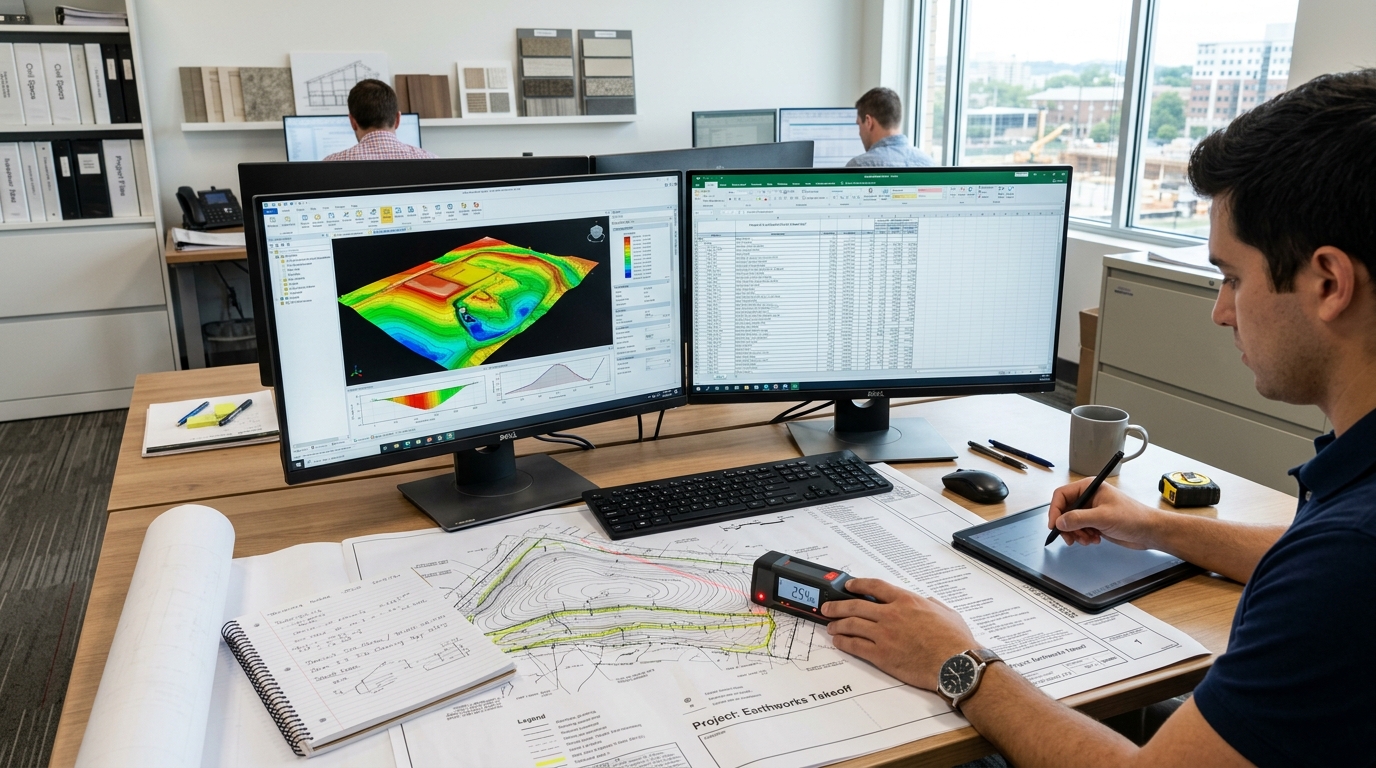
Using advanced digital modeling engines, our estimators digitize the site:
- Bare-Earth Baseline: We strip existing topsoil (4" to 8" site-wide) to establish the true excavation surface.
- Subgrade Surface Offsets: We build independent subgrade models beneath heavy-duty asphalt, standard parking, concrete sidewalks, building pads, and landscape beds.
- TIN Surface-to-Surface Comparison: Triangulated Irregular Network (TIN) modeling computes gross cut, gross fill, and net site balance.
- Utility Profiling: Tracing pipe centerlines, extracting structure depths, and categorizing trench volumes by OSHA depth brackets.
Senior QA Audit & Deliverables Package
Before delivery, a senior civil engineer reviews the model for common failure modes (e.g. inverted pipe slopes, unnoted rock refusal in boring logs, missing curb sections). Once verified, you receive your complete takeoff package:
Visual cut/fill depth contours, daylight boundary line, and spot elevation grid.
Unlocked CSI MasterFormat spreadsheet with dynamic formulas for unit pricing.
Behind the Scenes: Technical Preconstruction Protocols
Generating dependable quantities requires more than simply clicking contour lines. Here is how our civil modeling team prevents costly errors during every phase of takeoff production.
Scale Calibration & Datum Alignment
Before any polyline is traced, our estimators calibrate every individual sheet scale using known architectural dimensions, graphic bar scales, and surveyed property boundaries. When digital PDF sets have been scanned or re-exported through multiple architect-engineer revisions, non-uniform scaling distortions (where X-axis is 1"=20' but Y-axis is stretched to 1"=20.8') frequently occur. We verify scale across multiple coordinate quadrants to ensure zero area or volumetric distortion. Furthermore, we confirm the vertical datum (e.g. NAVD88 vs NGVD29) to eliminate 2-foot to 4-foot benchmark offsets.
Cross-Disciplinary Conflict Auditing
Civil site plans do not exist in isolation. Our workflow cross-checks civil grading and utilities against architectural floor plans (A-sheets), structural foundation schedules (S-sheets), and plumbing site utility connections (P-sheets). If the civil grading plan shows a finished floor elevation of 742.50' while the architectural building section specifies 743.00', we flag the half-foot discrepancy immediately. This prevents contractors from submitting bids based on flawed site balance calculations.
Differential Subgrade Offset Modeling
A major source of contractor dirt deficits is applying a uniform subgrade deduction across an entire site. Our 3D modeling workflow builds distinct subgrade surfaces tailored to each specific paving section: 4" asphalt over 8" stone base in truck loading areas (-12" offset), 2.5" asphalt over 6" stone in light-duty car parking (-8.5" offset), 4" concrete sidewalk over 4" stone base (-8" offset), and 6" topsoil respread in landscaped islands. Every surface boundary is modeled independently to produce true mass grading cut and fill yardages.
Trench Depth Stratification & Bedding
For underground utilities, linear pipe footage alone is meaningless without trench depth context. Installing 1,000 LF of 8-inch SDR-35 PVC pipe at a 5-foot depth requires basic equipment and standard trenching. Installing that same pipe at 14 feet requires hydraulic trench boxes, specialized excavator reach, and extensive backfill compaction testing. We stratify all wet utility lines into standard depth intervals (0-6', 6-10', 10-14', and 14'+) while calculating pipe zone bedding stone and surface restoration paylines.
Handling Addenda, Value Engineering & Bid Day Changes
Preconstruction is fast-paced and fluid. Here is how we support you when plans change in the final 48 hours before tender closing.
Rapid Addenda Delta Reports
When the design engineer issues an addendum altering parking lot grading, realigning storm sewer lines, or modifying curb radiuses, you do not have to wait days for updated numbers. We perform a computer-aided vector overlay against our baseline surface model. Within hours, you receive an itemized delta report highlighting exact quantity shifts (+320 CY cut, -85 LF RCP storm sewer, +140 SY heavy asphalt), enabling you to update your final bid spreadsheet with minimal stress.
Value Engineering (VE) Alternative Modeling
Looking to gain a competitive edge over rival bidders? We can evaluate grading alternatives, such as raising or lowering finished site grades by 6 to 12 inches to balance on-site cut and fill, eliminating expensive off-site soil export or import borrow trucking. Contractors use our comparative volume models to propose lucrative value engineering solutions to project owners.
Targeted RFI Formulation
When our takeoff team uncovers missing rim/invert elevations on utility sheets, ambiguous demolition boundary callouts, or contradictory geotech rock strata notes, we formulate clear, professional Request for Information (RFI) drafts. You can copy and submit these inquiries directly to the project architect or general contractor, protecting your firm from post-award change order disputes.
Frequently Asked Questions About Our Estimating Workflow
Standard commercial subdivisions, retail centers, and industrial warehouse sites ranging from 5 to 25 acres are typically modeled, audited, and delivered within 48 to 72 hours. Smaller 1-to-3 acre pad sites can often be turned around within 24 to 36 hours when requested for urgent bid deadlines.
We work with high-resolution PDF drawing sets daily. Our takeoff software allows us to calibrate drawing scales accurately, digitize vector contour lines, and extract structural elevations directly from PDF vector sheets without requiring raw DWG files from the civil engineer.
Put Our Estimating Process to Work for Your Next Bid
Upload your civil drawings today. We’ll review your project scope and have a proposal in your inbox quickly.